Notions, Coordinate-Systems and Sign Conventions#
Beams#
Beams are bent in the $x-y$ plane and the neutral axis in the unloaded configuration lies on the $x$ axis. The origin of the coordinate system is at the left support. When you specify the location of a concentrated force, you specify the distance of the point of application from the left support. When you are asking for the displacement at a point, you specify the distance of that point from the left support.
Sign conventions for loads of beams#
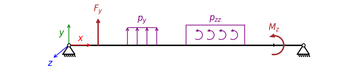
Fig. 1 Sign convention for beam loads in the x-y plane. The loads on the figure would have positive values.#
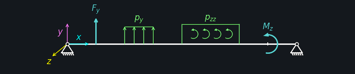
Fig. 2 Sign convention for beam loads in the x-y plane. The loads on the figure would have positive values.#
Sign conventions for internal forces and displacements of beams#
The positive meaning of the bending moment and the shear force can be read from the definitions
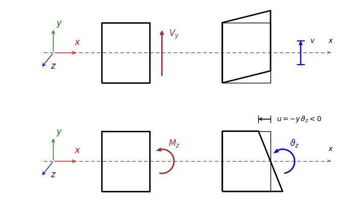
Fig. 3 Sign conventions for internal forces, couples, displacements and rotations for beams in the x-y plane. Quantities with a positive sign should be understood as they appear on the figure.#
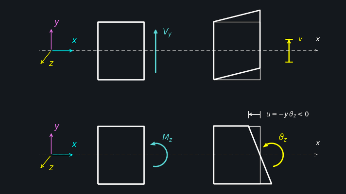
Fig. 4 Sign conventions for internal forces, couples, displacements and rotations for beams in the x-y plane. Quantities with a positive sign should be understood as they appear on the figure.#
Plates#
Plates are flat with a constant thickness and they lie in the x-y plane, with the reference surface ($z=0$) being the midsurface of the plate. The origin of the orthonormal, right-handed coordinate system is in the bottom-left corner. Whenever you specify the locations of loads or points for evaluating calculated quantities, you need to provide the coordinates wrt. this coordinate system.
Sign conventions for loads and displacements of plates#
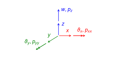
Fig. 5 Sign conventions for loads and displacement of plates.#
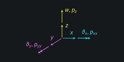
Fig. 6 Sign conventions for loads and displacement of plates.#
Sign conventions for internal forces of plates#
The internal forces for a plate of constant thickness $t$ are defined as:

Fig. 7 Bending in the XY plane.#

Fig. 8 Bending in the XY plane.#

Fig. 9 Bending in the XZ plane.#

Fig. 10 Bending in the XZ plane.#

Fig. 11 Twisting.#

Fig. 12 Twisting.#